 ultimate-guide
Structural Requirements for Aluminium Facade Systems
Last Updated: November 7, 2026
Quick Summary
Structural requirements for an aluminium facade system require every panel, mullion and bracket to pass wind, dead and live loads to the building frame along a continuous, calculable load path. Each link needs a documented capacity, and wind pressure must be calculated per zone, not as one blanket figure.
- Load travels from panel to subframe, bracket, anchor, then slab or structural steel.
- Wind pressure depends on terrain category, building height, shielding and local pressure factors.
- Mullion deflection above the project limit requires greater depth, thicker walls or reduced support spacing.
- Brackets must allow movement without transferring load into the slab and isolate dissimilar metals.
- Specify inspection points on drawings so connections are checked before panels close them in.
Table of Contents
- How Aluminium Facade Systems Carry Load
- Aluminium Facade Wind Load Requirements
- Facade Bracket and Fixing Design
- Building Movement Joints in Facades
- Facade Shop Drawings Structural Details
- Panel Materials, Alloys and Strength-to-Weight Performance
- Submitting Your Facade Documentation to BluePrint Facade
- Frequently Asked Questions
How Aluminium Facade Systems Carry Load
Structural requirements for aluminum facade systems begin with one principle: every panel, mullion and bracket must pass its load to the building frame along a continuous, calculable path. Get that path wrong and no amount of premium cladding rescues the design. The failures seen on facade projects rarely start at the panel. They start at the connection nobody detailed.
An aluminium facade system is a framed assembly of cladding panels, vertical and horizontal profiles, brackets and anchors that forms the building envelope and transfers wind, dead and live loads back to the structure.
The Load Path from Panel to Building Frame
Load travels in one direction only: panel to subframe, subframe to bracket, bracket to anchor, anchor to slab or structural steel. Each link needs a documented capacity. A common mistake is specifying a bracket that is strong enough in isolation but bolts to a slab edge with insufficient edge distance, so the concrete, not the steel, governs the design.
Where the facade meets the structure, the interface must tolerate construction tolerance. Support spacing, anchor type and slotted connections all decide whether that interface works in practice. We treat the load path as the backbone of every drawing set we produce.
Watch out: if the load path is not drawn and dimensioned on the shop drawings, site teams guess, and RFIs follow.
Aluminium Facade Wind Load Requirements
Wind governs most facade design in this market, and it is the load case that most often drives panel span, mullion depth and fixing size. Wind pressure on a facade depends on the site's terrain category, building height, shielding and the local pressure factors for edges and corners, which is why a single "design wind pressure" figure applied across a whole elevation is a red flag in any drawing set.
Working Through a Wind Pressure Calculation
The wind pressure calculation is carried out in the following sequence, with the wind actions determined under the relevant Australian wind loading standard:
- Determine the regional wind speed for the site from the applicable Australian wind loading standard.
- Apply terrain, height and shielding multipliers for the actual surroundings.
- Calculate design wind pressure for the specific surface, including internal pressure.
- Apply local pressure factors at corners, edges and roof junctions.
- Compare the result against the panel and mullion capacity from the manufacturer's test data.
The output is a set of pressures per zone, not one number. Any facade design requirements schedule should show those zones on the elevation.
Quantified Design Checks and Worked Criteria
A calculation sequence is only useful if it ends in numbers a fabricator and certifier can check.
Design wind pressure check. The schedule should show the design pressure, the zone, and the local pressure factor applied for each zone, rather than a single blanket number.
Mullion deflection check. Serviceability limits for mullions under wind are set by the project specification.
Panel span and fixing check. Panel spans are limited by the panel's tested capacity and the fixing spacing.
Anchor and bracket capacity check. The connection must resist the combination of wind, dead load and thermal movement. The check must use the actual edge distance and substrate, not the catalogue maximum.
Local Pressure Factors and Zone Mapping
Local pressure factors are where most simplified calculations fall short. Higher pressures apply at corners, edges and roof junctions because wind accelerates around those discontinuities. A facade elevation should be divided into zones, with each zone assigned its own pressure and its own panel and fixing check. The zone map belongs on the shop drawing, not buried in a calculation report, so the installer knows which panels and fixings go where.
For a deeper walk through wind load, movement joints and NCC 2022 evidence, see our guide to structural compliance for complex facade designs.
Facade Bracket and Fixing Design
Brackets and fixings decide whether the calculated loads actually reach the structure. Design each connection for the combination of wind, dead load and thermal movement, then check the weakest element: the anchor, the bracket, the weld or the substrate.
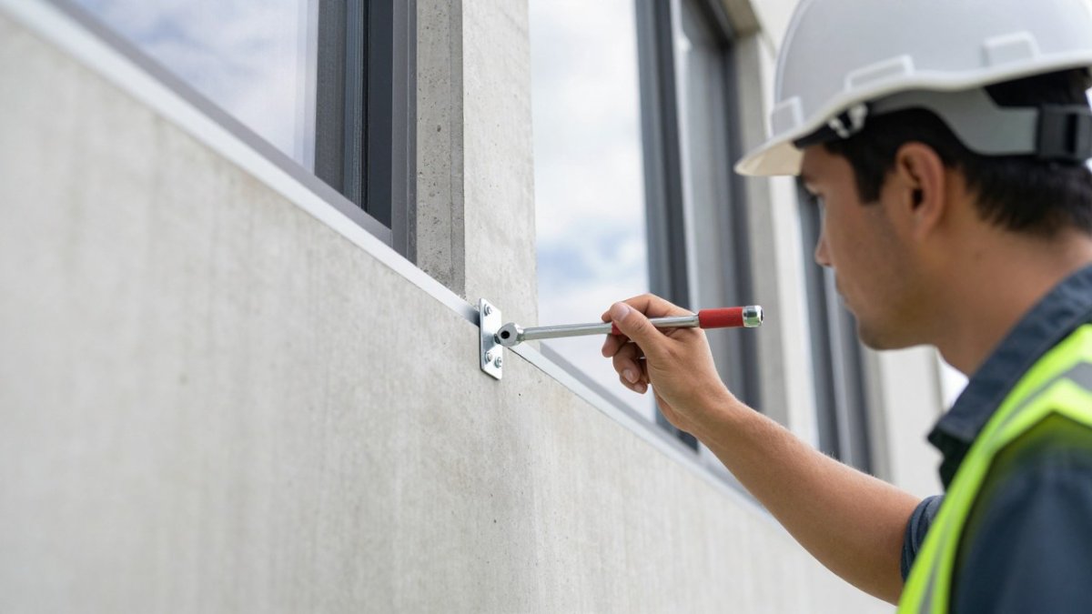
The details that matter most:
- Anchor type and edge distance: cast-in vs post-installed anchors have different capacity and tolerance profiles.
- Slotted and serrated connections: these allow adjustment during installation without losing shear capacity.
- Isolation: dissimilar metals need separation to control corrosion.
- Movement accommodation: brackets must allow the facade to move without transferring load into the slab.
Connection Failure Modes
Most guides stop at the design calculation.
Anchor pull-out. The anchor pulls out of the concrete when the edge distance is too small, the substrate is weaker than assumed, or the hole is drilled oversize.
Pull-over. The anchor stays in the concrete but the bracket or washer pulls over the anchor head.
Corrosion. Dissimilar metals in contact, or a coating damaged during installation, create a corrosion cell.
Fatigue. Wind pressure cycles, especially at corners and edges, can fatigue welds or thin brackets over time.
Installation defects. Missing washers, over-torqued or under-torqued bolts, slotted connections left loose, and anchors installed at the wrong edge distance are the most common site defects.
Inspection and Testing
Specify the inspection points on the drawings. A practical inspection schedule covers:
- Pre-installation: confirm anchor type, bracket size and isolation washers match the schedule.
- During installation: check edge distances, torque values and slot positions before panels are fixed.
- Post-installation: sample torque checks, visual inspection for corrosion and movement, and confirmation that movement joints are free.
Where the connection is critical or the substrate is uncertain, on-site pull tests of post-installed anchors are a common verification method. The test load and acceptance criteria should be stated in the specification, not left to the installer.
Watch out: if the inspection points are not on the drawings, the site team has no trigger to check the connection before the panels close it in, and the defect is hidden for the life of the building.
What most guides miss is inspection. Connection failure modes, such as anchor pull-out, weld cracking and loosened fixings, are found by routine site inspection, not by the design calculation. Specify the inspection points on the drawings.
Building Movement Joints in Facades
Buildings move. Slabs deflect, structures sway, and aluminium expands and contracts with temperature far more than concrete or steel. Movement joints in facades absorb that movement so it does not crack panels, break seals or load the fixings.
Design joints at every interface where movement is expected: between facade and structure, between facade and other trades, and at regular intervals along long elevations. Thermal movement in aluminium is significant over long runs, so the joint width must be calculated, not guessed from a standard detail. Serviceability limits, including deflection of mullions under wind, belong in the same conversation. A facade that is strong enough but deflects visibly will fail on weathertightness and occupant comfort.
Facade Shop Drawings Structural Details
Shop drawings translate the engineer's design into buildable detail, and they are where structural requirements either survive or get lost. A facade shop drawing set must show the structural details clearly enough that a fabricator can build and a certifier can check.
Every set should document:
- Mullion and transom profiles, with the structural capacity stated against the design pressures.
- Bracket and anchor schedules, with type, size, spacing and edge distance.
- Connection details at slab edges, head and sill, and movement joints.
- Glazing dimensions and panel sizes, matched to the panel span assumptions.
- Installation sequence where the structure dictates the order of works.
For examples of what each sheet should show, see our facade shop drawing examples, and for the drafting method itself, our guide on creating curtain wall facade shop drawings covers mullion profiles, glazing dimensions and installation sequences.
Panel Materials, Alloys and Strength-to-Weight Performance
Aluminium's advantage is its strength-to-weight ratio: a solid or interlocking panel system can span meaningful distances while keeping dead load on the structure low. That matters because lighter cladding reduces demand on the building frame and on the anchors.
Material selection drives structural capacity as much as profile geometry does. Specify the aluminium alloy and temper, the panel thickness and the finish, because each affects strength and corrosion resistance. Fire safety is part of the same specification, and evidence of conformity with the applicable requirements must be documented. Those requirements are set out in the National Construction Code, and the wind and structural standards the design relies on are published by Standards Australia.
| Element | What to specify | Why it matters |
|---|---|---|
| Alloy and temper | Grade and heat treatment | Governs strength and formability |
| Panel thickness | Nominal and tolerance | Drives span and deflection |
| Profile geometry | Mullion depth, wall thickness | Sets structural capacity |
| Finish | Coating system | Corrosion resistance and durability |
| Fire performance | Non-combustible evidence | NCC compliance |
Submitting Your Facade Documentation to BluePrint Facade
The final step is documentation that proves the structural requirements are met, in a form a certifier and fabricator can both use. That means coordinated drawings, clear load paths, and details that match the calculations.
This is where we work. Our facade engineering services explain the scope. If you are ready to move, our facade and window shop drawings service is where projects start.
The structural requirements for aluminium facade systems are unforgiving: one weak connection or one missing movement joint can undo an otherwise sound design. If your next project needs documentation that stands up to certifier scrutiny and site reality, we can help.
Frequently Asked Questions
What structural loads must an aluminium facade system withstand?
An aluminium facade carries its own dead load, wind pressure acting inward and outward, and the effects of building movement such as floor deflection and thermal expansion. It must also resist lateral loads from seismic or impact events where relevant, and transfer all of this through brackets and anchors into the building frame. Designers check each load case against the structural capacity of panels, vertical profiles and connections, keeping deflection within serviceability limits so glazing and weather seals are not compromised.
What Australian standards apply to aluminium facade systems?
Wind actions, combination factors, aluminium structural design, glazing selection and fire performance are each addressed by the applicable Australian standards and the National Construction Code. Your project's facade engineer should map each element and connection to the applicable standard, and the shop drawings should reference them so the builder and certifier can verify compliance.
How do engineers account for building movement in facade design?
Movement joints are set at calculated spacing to absorb thermal expansion of aluminium profiles, concrete slab deflection and inter-storey drift. Each joint needs a defined gap width, a compatible sealant or gasket, and a slip connection that allows movement without transferring load into the panels. Designers calculate the expected movement range from temperature differentials and structural deflection, then size the joint so it never closes completely or opens beyond the seal's capacity under the worst-case combination.
What structural information should facade shop drawings include?
Shop drawings should show bracket types, anchor specification and embedment, support spacing, panel spans, connection details at slab edges and movement joints, and the fixing schedule with torque values. They should also reference the design actions, deflection limits and standards the system has been checked against. Clear, dimensioned details at every interface, including head, sill and jamb conditions, reduce requests for information on site and give the certifier a traceable record of how the facade meets its structural requirements.
How can structural performance be verified before facade installation?
Verification combines engineering calculation with physical testing. Calculations confirm panel spans, bracket capacity and connection strength against the design wind pressure and movement allowances. Physical testing, such as air and water penetration tests and structural performance tests on a mock-up, confirms the assembled system behaves as designed. Reviewing shop drawings against the engineer's design before fabrication starts catches detailing errors early, which is far cheaper than correcting fixings or joints after panels are on the building.