 how-to
Facade Shop Drawing Examples and What Each Sheet Shows
Quick Summary
A facade shop drawing is the detailed technical drawing that turns an architect's design intent into dimensions a fabricator can build and an installer can fix to a building. A typical set is a numbered package covering the cover and register, plans, elevations, sections, details, schedules and anchor connections, each checked against the next.
- Facade shop drawings specify mullion profiles, glazing sizes, anchor positions, sealant joints and installation sequence.
- The cover sheet and drawing register list every sheet with its current revision.
- Opening sizes on elevations should match the opening schedule before review proceeds.
- Anchors and connection details need load paths noted so the structural engineer can confirm them.
- Phrases like "by others" or "to suit" signal an unassigned responsibility and should be resolved before issue.
Table of Contents
- A Complete Sample Facade Shop Drawing Set, Sheet by Sheet
- Facade Shop Drawing Details Worth Studying in Examples
- Curtain Wall Shop Drawings: Examples of Glazing, Anchors and Interfaces
- Facade Drawing Symbols and Sections: Reading the Annotations
- Facade Shop Drawing Review Checklist and Common Errors
- Booking a Drawing Review or Documentation Package With BluePrint Facade
- Frequently Asked Questions
What Facade Shop Drawings Are and Why They Matter
Facade shop drawings are the detailed technical drawings that turn an architect's design intent into something a fabricator can build and an installer can fix to a building.
The architect's documents show what the building should look like; the shop drawings show how it will be made.
Here is the core job of a shop drawing set in plain terms:
- Translate design intent into dimensions a fabricator can cut to
- Coordinate interfaces between the facade, the structure and the building services
- Show connections that the architect's general drawings leave out
Many teams treat shop drawings as an admin task, but they carry much of the project's risk.
A Complete Sample Facade Shop Drawing Set, Sheet by Sheet
A facade shop drawing set is a numbered package where each sheet has a job and a place in the sequence. Reading it in order shows how one design decision travels from the architect's intent down to a fabrication instruction.
A useful test for any sheet: can the fabricator build the part shown without calling anyone? If not, the sheet is not ready for issue.
Cover Sheet and Drawing Register
The first sheet is the control document: project name, facade package reference, revision status and a drawing register listing every sheet with its current revision.
A register that does not match the revision stamped on each sheet makes it hard for a reviewer to confirm what they are signing off.
General Arrangement Plans
Plan sheets cut horizontally through each floor and show the facade in relation to the slab edge, column lines, structural setouts and internal finishes, establishing the geometric framework everything else hangs from.
The plan is where interface clashes first become visible. A plan that shows the facade anchor line without the structural edge beam, or without the services riser passing through the same zone, hides a problem that will surface on site.
Elevations
Elevation sheets show the external face of the facade with grid lines, panel divisions, opening types and reference markers. They are the sheet the site team reads most often, because they show what the finished wall looks like and where each panel sits.
Checking that the opening sizes on elevations match the opening schedule at the start of review helps catch mismatches before they reach the fabricator.
Sections
Section sheets cut vertically through the wall from slab to roof and show the profile build-up: mullion depth, insulation, glazing bite, head and sill conditions, and the relationship between the facade and the structural frame.
Sections should also show movement joints and their allowance, because thermal and seismic movement is a design decision, not a site adjustment.
Detail Sheets
Detail sheets zoom into the points where components meet: mullion to transom, panel to anchor, facade to roof, facade to balcony, and facade to adjacent wall type.
Detail sheets are also where responsibility is assigned. A detail that says "sealant by others" without naming who "others" is has not assigned the responsibility; it has deferred it.
Schedules
Schedules are the tabular backbone of the set. They list panels, glass types, hardware sets, sealants and anchors by mark, with quantities and specifications. A schedule is only useful if its marks match the elevation and detail callouts exactly. When a panel mark on the elevation does not appear in the schedule, the fabricator cannot order the glass.
Connection and Anchor Details
Anchor and connection details show where each fixing sits relative to the slab, column and embedded plates, with load paths noted so the structural engineer can confirm them. These sheets are the bridge between the facade package and the structural package, and they are the most frequent source of requests for information when incomplete.
How the Sheets Work Together
The sequence matters because each sheet depends on the one before it. The plan sets the grid; the elevation sets the panel layout against that grid; the section proves the profile fits the zone; the detail resolves the connection; the schedule lists what to buy. If any link is inconsistent, the fabricator is left to guess, and guessing is where rework starts.
The sheets in a typical package each have a defined job, and the register-to-schedule sequence can be scanned at a glance:
| Sheet | What it shows | Check for |
|---|---|---|
| Cover and register | Package reference, revisions, issued sheets | Register matches sheet revisions |
| General arrangement plans | Facade against slab edge and column lines | Grid references match the architect's set |
| Elevations | External face, panel divisions, opening types | Opening sizes match the opening schedule |
| Sections | Profile build-up from slab to roof | Mullion fits the available zone |
| Detail sheets | Points where components meet | Responsibilities are named, not deferred |
| Schedules | Panels, glass, hardware and anchors by mark | Marks match elevation and detail callouts |
| Anchor and connection details | Fixings relative to slab and column | Load paths noted for the structural engineer |
Facade Shop Drawing Details Worth Studying in Examples
Studying real details teaches more than reading definitions. The details below are the ones reviewers return to most often, because errors tend to cluster there.
- Head and sill conditions where the wall meets the floor slab, showing how movement and drainage are handled
- Corner conditions where two facade planes meet, which often carry the tightest tolerances
- Transom and mullion joints, showing the thermal break and the gasket locations
Curtain Wall Shop Drawings: Examples of Glazing, Anchors and Interfaces
Curtain wall shop drawings focus on how glass and framing are assembled into a continuous envelope.
Glazing. Sheets should list each glass build-up with its thickness, coating and spacer type, along with the edge bite into the frame.
Anchors. Anchor drawings show where each fixing sits in relation to the slab, the column and any embedded plates.
Facade Drawing Symbols and Sections: Reading the Annotations
Facade drawings use a shared language of symbols, section markers and annotations. Learning it speeds up review considerably.
- Section cut markers show where a section is taken and which way it looks
- Detail bubbles link a callout on an elevation to a numbered detail
- Material hatches distinguish glass, aluminium, concrete and insulation
Annotations should be short and unambiguous. Phrases like "to suit" or "by others" are warning signs that a responsibility has not been assigned, and they should be resolved before the drawing is issued for construction.
Facade Shop Drawing Review Checklist and Common Errors
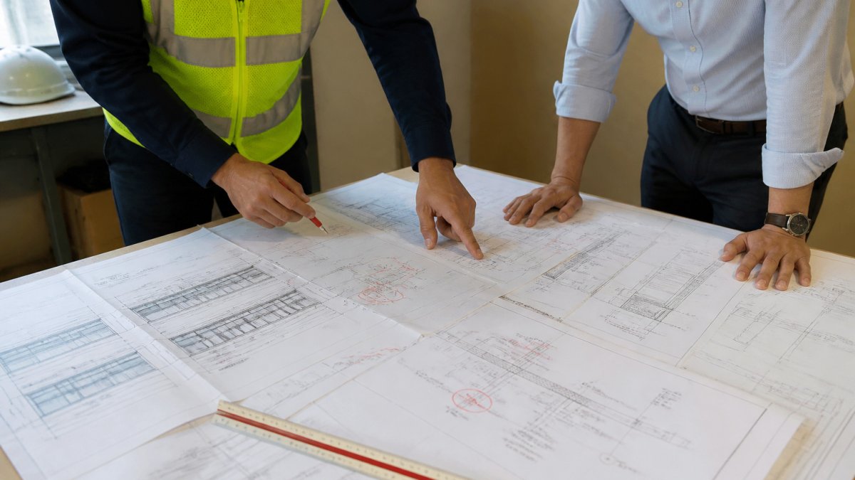
A structured review catches most errors before they reach the site, but only if the reviewer knows what each check is protecting against. The checklist below is organised by risk, with the consequence of a missed check noted alongside it.
Dimensional Consistency
- Grid lines and reference marks match the architect's drawings exactly
- Dimensions agree between plans, elevations, schedules and details
- Opening sizes on elevations match the opening schedule
A dimension that does not add up across sheets is the most common error in any set. Its consequence is a fabricated panel that does not fit, discovered only when it arrives on site. Because panels are cut to the drawing, a 50 mm error on a schedule becomes a 50 mm error in aluminium.
Movement and Tolerance
- Glazing sizes allow for thermal movement and manufacturing tolerance
- Movement joints are shown with their allowance stated
- Anchor slots allow for the movement the structure will experience
Facade systems move: glass expands and contracts, aluminium deflects, and the structure itself moves under load. A glazing bite with no allowance for movement will produce either a cracked pane or a leaking joint within the first seasonal cycle.
Structural Interface
- Anchor positions are confirmed by the structural engineer
- Load paths are noted on anchor and connection details
- Embedded plates and their tolerances are shown
An anchor shown without a load note is an unconfirmed assumption. The facade contractor may design the fixing, but the structural engineer must confirm the load it transfers into the slab. When this check is skipped, the fixing is designed twice and the second design often arrives after fabrication.
Water Management
- Drainage paths are shown through head, sill and transom conditions
- Weep holes and baffles are detailed
- Sealant and gasket types are specified for each joint
Water management is where facade details earn their keep. A head detail that shows a sealant joint but no drainage path will trap water against the frame. The consequence is not visible at handover; it appears as a leak months later.
Interface Responsibility
- Every trade interface has a named responsible party
- "By others" notes are resolved or escalated before issue
- Roof, balcony and adjacent wall junctions are shown on one sheet
Phrases like "to suit" and "by others" are warning signs that a responsibility has not been assigned. A facade-to-roof junction drawn by the facade contractor and separately by the roofing contractor, with neither showing the other's work, is a gap that becomes a site argument.
Revision Control
- Revision clouds match the revision register
- Superseded sheets are withdrawn from site
- Requests for information are closed against the current revision
A revision cloud that marks a change not recorded in the register means the site team cannot tell which version is current. The consequence is installation to a superseded detail, which is expensive to reverse once panels are fixed.
Constructability
- The sequence of installation is achievable with the details shown
- Fixings are accessible with the tools the installer will use
- Tolerances are achievable with the specified system
A detail can be dimensionally correct and still be unbuildable. An anchor behind a fixed transom, or a sealant joint the installer cannot reach, forces a site modification that departs from the approved drawing. Reviewing for constructability means asking how the installer will actually reach and fix each component.
Common Errors and Their Consequences
Many review errors share a pattern: they are generally cheaper to fix on screen than on site.
- Dimensions that do not add up across sheets lead to fabricated panels that do not fit.
- Missing thermal break details lead to condensation and energy performance failure.
- Anchors shown without load notes lead to unconfirmed structural assumptions.
Watch out: a drawing that looks complete can still hide a clash. Overlay the facade with the structure and services before issue, not after. The overlay is the only check that catches a facade anchor passing through a structural beam or a services penetration landing inside a mullion, because each package's drawings can be internally consistent while conflicting with each other.
Booking a Drawing Review or Documentation Package With BluePrint Facade
If your team needs a second check on a facade set, or a full documentation package from the start, BluePrint Facade can help.
For current pricing, prices depend on project scope, quantity and delivery timing, so please request a quote. Visit our facade and window shop drawings page to see the service in more detail and submit your project details.
Last Updated: November 3, 2026
Frequently Asked Questions
What should facade shop drawings include?
Facade shop drawings typically include plan, elevation and section views at a scale suited to each detail, panel layouts, anchor and bracket positions, glazing and gasket details, material profiles, dimensions and tolerances, and interface details with the structure and adjacent trades. Each sheet should carry a revision number and a clear title block. A complete set lets the fabricator cut and assemble components and lets the installer set them in place without guessing. Check with your project documentation requirements and the specification for the exact sheet list, since scope varies by project and by the systems being used.
What is the difference between facade design drawings and shop drawings?
Design drawings show the architect's intent for the facade: its form, appearance, general materials and how it sits on the building. Shop drawings translate that intent into fabrication and installation information, with the detail needed to manufacture and fix each component. Design drawings are usually at a broader scale, while shop drawings resolve connections, profiles, dimensions and sequencing. Shop drawings are normally prepared by the specialist facade contractor or documentation provider and reviewed against the design before fabrication proceeds.
How do you read facade shop drawings?
Start with the general notes and the drawing index, then read the plan and elevation sheets to locate each zone. Use the section and detail sheets to understand how components connect, and cross-reference the symbol legend for anchors, glazing types and finishes. Check dimensions against the grid and confirm which datum is used. Compare the interface details with the structural and architectural drawings to find clashes. Reading is faster when you work through one panel type at a time rather than sheet by sheet.
What common errors should be checked in facade shop drawings?
Common errors include dimensions that do not match the structural grid, missing thermal movement allowances, incorrect glazing or gasket specifications, anchors that clash with services, and drainage paths that are not continuous. Interface details with slabs, columns and roof edges are frequent problem areas. Check that revision clouds match the latest design changes and that every referenced detail exists in the set. A structured review checklist catches most of these before fabrication.